
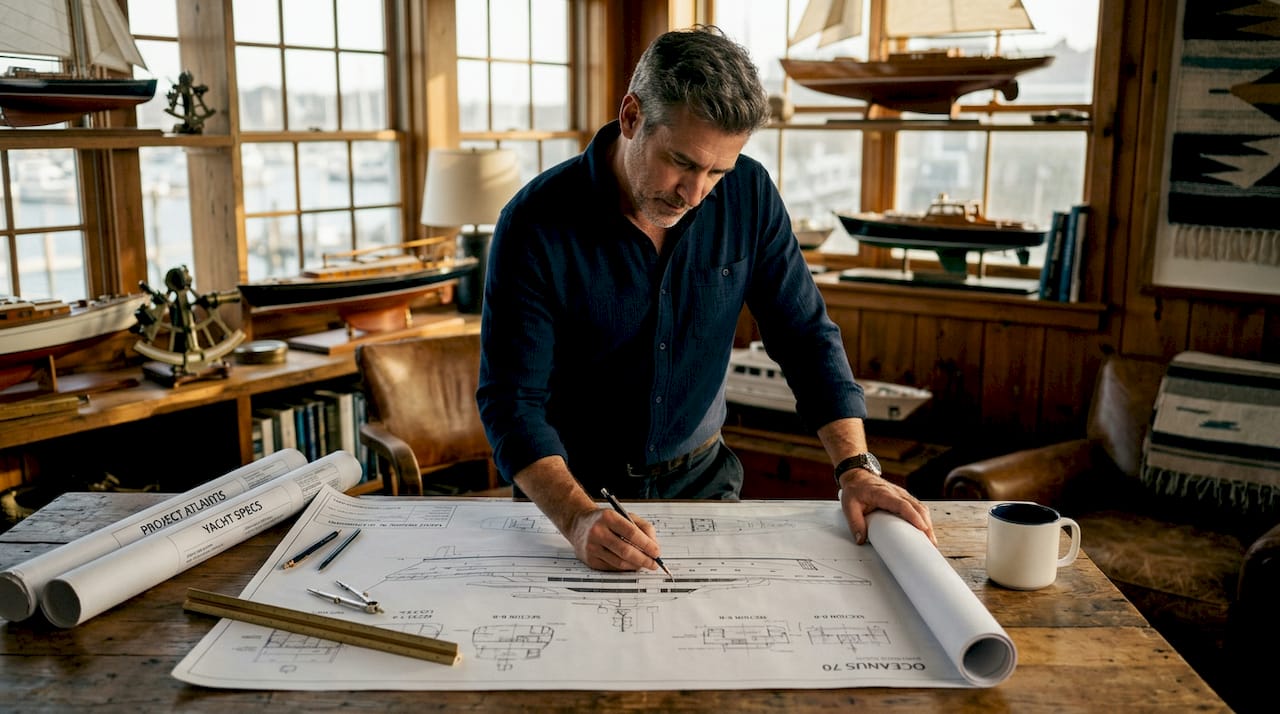
Yacht blueprints can stop a first-time builder or enthusiast dead in their tracks. Pages of lines, numbers, and cryptic symbols that seem to demand a naval architecture degree just to parse. Yet knowing how to read yacht blueprints is not reserved for professionals. With the right framework, you can decode what each drawing communicates, understand how the pieces connect, and engage with the design process at a genuinely informed level. This guide walks you through the core blueprint types, how scale and symbols work, and a methodical approach to reading the two drawings that matter most.
Table of Contents
- Key takeaways
- How to read yacht blueprints: the core document types
- Scale, symbols, and annotations
- Reading the General Arrangement plan
- Decoding the Lines Plan
- Cross-checking dimensions and avoiding errors
- My honest take on learning to read blueprints
- Build your vision with Baranof Yachts
- FAQ
Key takeaways
| Point | Details |
|---|---|
| Start with blueprint types | GA plans, Lines Plans, and structural drawings each serve a distinct purpose and must be read together. |
| Scale before anything else | Identify the drawing scale first to convert measurements into real-world dimensions accurately. |
| GA as your spatial anchor | The General Arrangement plan orients you to every other drawing by mapping function and flow across decks. |
| Lines Plan reveals hull geometry | Three 2D projections work together to fully define the 3D hull shape and its performance characteristics. |
| Cross-check everything | Dimensions and notes must be verified across multiple views to catch errors and confirm accurate interpretation. |
How to read yacht blueprints: the core document types
Before you read a single line, you need to know what type of drawing you are looking at. Yacht design packages typically contain several distinct drawing categories, and each one communicates a specific layer of information. Treating them as interchangeable is one of the most common errors early readers make.
Here are the primary blueprint types you will encounter:
- General Arrangement (GA) plan. The GA provides a deck-by-deck layout showing the spatial relationship between all major areas: cabins, saloons, engine rooms, helm stations, and deck equipment. It is the most immediately readable drawing in the package and your primary orientation tool.
- Lines Plan. This is the technical heart of the design. It presents the hull geometry through three orthogonal 2D views: the body plan, sheer plan, and half-breadth plan. Together, these three projections define the hull surface completely and form the geometric foundation for stability, hydrostatics, and all construction drawings.
- Structural section drawings. These show how the hull and superstructure are built at specific cross-sections: frame spacing, bulkhead placement, laminate schedules, and reinforcement details. They answer the “how is this held together?” question.
- Systems schematics. Electrical single-line diagrams, plumbing layouts, fuel and water diagrams, and HVAC routing all fall into this category. They are read differently from spatial drawings and rely heavily on standardized symbols.
No single drawing tells the full story. Each view type reveals distinct information: layout, length and height relationships, and internal structure. The skill in reading marine blueprints lies in understanding how these documents reinforce and constrain each other.
Scale, symbols, and annotations
Every blueprint is drawn to a stated scale, and that scale is the first piece of information you must locate. A drawing marked 1:50 means that one unit on paper equals 50 of the same units in reality. If you measure 20 millimeters on the plan, the real-world dimension is 1,000 millimeters, or one meter.
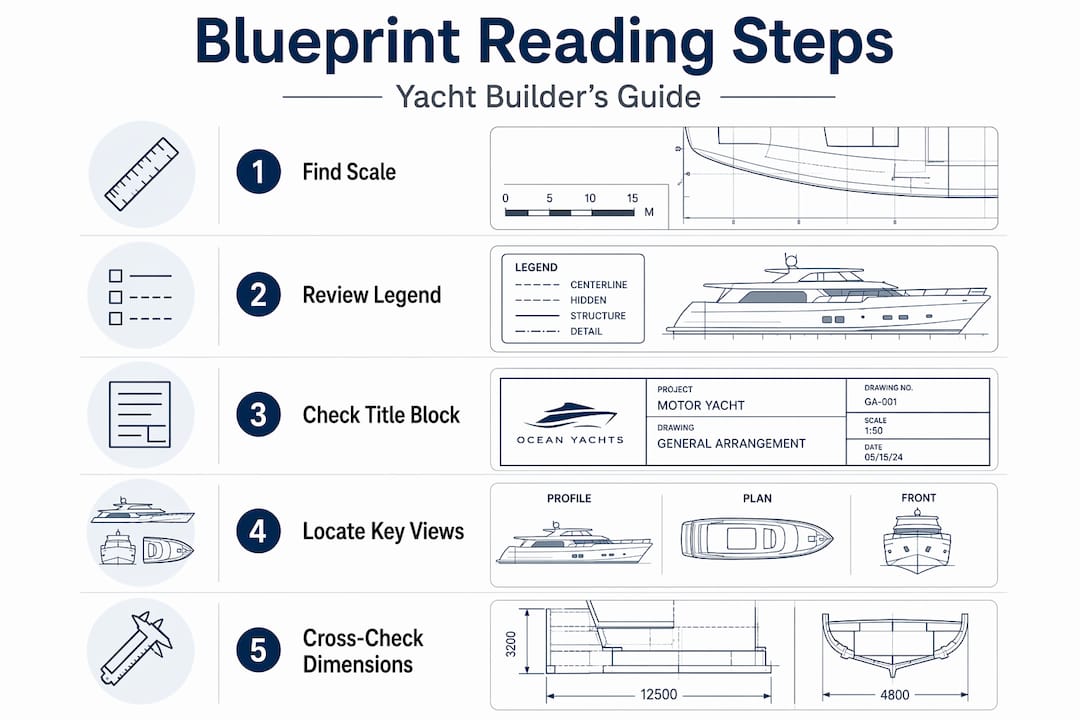
Identifying the scale first is not optional. It is the single step that makes every other measurement meaningful. Yacht construction blueprints use a range of scales depending on the drawing type: GA plans often use 1:100 or 1:50, while detailed structural sections may be drawn at 1:20 or even 1:10 to show fine construction details clearly.
Beyond scale, every professional drawing set carries a legend or key. Here is what to look for and how to treat it:
- Material callouts. Hatching patterns identify different construction materials. Steel, aluminum, fiberglass, teak, and foam core all have distinct representations. Never assume.
- Fixture and equipment symbols. Standard symbols represent anchors, winches, fire suppression equipment, sea cocks, and hatches. Legends and keys decode these symbols and must be read as a core part of the drawing, not a footnote.
- Construction notes. Notes in the title block or scattered across the drawing are instructional. They specify tolerances, material grades, installation sequences, and approval requirements.
- Revision history. The title block records every revision the drawing has gone through. Always confirm you are reading the latest approved revision before making any measurements or decisions.
Pro Tip: When reading any new drawing, spend two minutes with the legend and title block before looking at the plan itself. This prevents the classic mistake of misidentifying a symbol and carrying that error forward across your entire interpretation.
Reading the General Arrangement plan
The GA plan is where most people should start, and for good reason. It gives you the spatial logic of the whole yacht before you drill into any technical detail. Think of it as the conductor’s score before the individual instrument parts: it shows how everything fits together and where the tempo changes.
Here is a methodical approach to reading the GA from the ground up:
- Orient yourself to the plan view. The GA typically presents a top-down (plan) view of each deck. Identify bow (forward) and stern (aft) first. Every other spatial relationship depends on this orientation.
- Read deck by deck, from the keel up. Start at the lowest deck or bilge level and work upward. Note the placement of the engine room, tankage, and structural bulkheads before moving to accommodation decks.
- Map the flow between spaces. GA plans must be read as a coordinated system linking spaces and equipment, not as isolated labeled rooms. Ask yourself: how does crew move from the galley to the helm? How does a guest access the aft deck from their cabin? Circulation paths reveal design intent.
- Locate operational and safety features. Mark fire extinguisher stations, life raft stowage, sea cock locations, and emergency exits on your mental map. These positions in the GA will anchor your reading of systems schematics later.
- Note equipment placement relative to structure. Winch positions, mast steps, windlass mounts, and generator sets are all shown in the GA. Their placement has knock-on effects for structural and electrical drawings.
Pro Tip: Use the GA as your spatial anchor every time you switch to a new drawing type. When a systems schematic shows a pump in zone 3, go back to the GA and physically locate zone 3 before reading further. GA reading serves as a spatial anchor when interpreting detailed system schematics, making complex navigation far more manageable.
Decoding the Lines Plan
The Lines Plan is where yacht design interpretation shifts from intuitive to technical. This is also where it gets genuinely fascinating, because these three 2D views collectively describe a three-dimensional form with mathematical precision.
| View | What it shows | Key terms to know |
|---|---|---|
| Body plan | Cross-sections of the hull at defined stations, viewed from forward and aft simultaneously | Stations, frame lines, deadrise angle |
| Sheer plan | A side (profile) view showing waterlines, buttock lines, and deck sheer from bow to stern | Buttocks, waterline intersections, sheer line |
| Half-breadth plan | A top-down view showing waterline curves and deck edge from centerline to one side | Waterlines, half-breadths, maximum beam |
To visualize the 3D hull from these flat projections, you need to understand how the three views interlock. Every point on the hull appears in all three views simultaneously, just projected onto a different plane. A station line in the body plan corresponds to a vertical slice that also appears as a line on the sheer plan. A waterline in the half-breadth plan is a horizontal slice that intersects both the body plan and sheer plan at a defined height.

The Lines Plan projections are mathematically mutually constraining. If you read a dimension from the body plan at station 5, that same dimension must be consistent in the sheer plan and half-breadth plan at the corresponding location. Any discrepancy means either a drafting error or, more commonly, that you have misidentified your station or waterline reference.
For those pursuing hull design fundamentals, the body plan is particularly telling. A deep, narrow body plan section indicates a stiff, seaworthy hull. A wide, shallow section suggests stability through beam rather than depth, which carries different performance characteristics in offshore conditions.
Pro Tip: Print or trace individual station lines from the body plan onto tracing paper. Hold them against the sheer plan at the corresponding station location. If they align, your reading is consistent. If they do not, you have misidentified a reference line, and everything downstream of that error needs to be re-read.
Cross-checking dimensions and avoiding errors
Reading any single drawing in isolation is a shortcut to misinterpretation. The professional approach to reading marine blueprints always involves cross-referencing dimensions across at least two views before acting on a measurement.
Cross-checking dimensions across drawings is the single most reliable safeguard against errors. Here is how to build that habit:
- Identify the same feature in multiple views. If the GA shows a bulkhead at frame 12, find frame 12 in the structural section and confirm the bulkhead position and construction detail match.
- Check that sectional views align with stated stations. Sections in construction drawings correspond to specific stations defined in the Lines Plan. A misidentified station can mean reading the wrong cross-section for a bulkhead or frame entirely.
- Treat inconsistencies as signals, not nuisances. When a dimension in one drawing does not match the same feature in another, the cause is usually one of three things: a drawing revision that was not carried across the full set, a deliberate design change in one view that was not yet updated elsewhere, or a misread reference line on your part.
- Read construction notes before measuring. Notes often specify governing dimensions, tolerances, and override conditions. A note stating “hold dimension at frames 6 through 9” means the drawing measurement there is exact, while adjacent dimensions flex to accommodate.
- Verify dimensional data consistency before material sourcing. In custom builds, ordering materials based on a single unverified measurement from one view is a costly error. Cross-check first.
My honest take on learning to read blueprints
I will tell you exactly where I went wrong when I first approached yacht blueprints: I tried to read everything at once. I spread the full drawing set across a table and attempted to take in the GA, the Lines Plan, and three structural sections simultaneously. It was like trying to read a novel by opening random pages.
What changed my understanding was learning to treat the GA as the primary document and everything else as commentary on it. Once I understood where the engine room sat relative to the accommodation, where the main bulkheads ran, and how the deck layout distributed weight and function, every other drawing started to make sense as an elaboration of that foundation.
The Lines Plan was the second shift. I had assumed it was purely a designer’s tool and not something a builder or enthusiast needed to parse. That assumption was wrong. Reading the body plan taught me more about why a hull behaves the way it does in a seaway than any performance specification sheet ever did. The shape of the sections at midship and at the bow told the whole story of how that vessel would handle waves, load distribution, and stability.
My honest advice: start with one drawing type at a time. Master the GA before touching the Lines Plan. Accept that this is a skill built through repeated practice, not a single reading session. The payoff is that you will be able to walk into any design review or pre-build consultation and contribute meaningfully, not just nod along.
— Jason
Build your vision with Baranof Yachts

At Baranofyachts, we work with clients who arrive at the design table with everything from rough sketches to fully resolved blueprint packages, and we meet each one exactly where they are. Understanding yacht plans is a skill that pays dividends long before the first piece of material is cut. Our team brings that same meticulous eye to every custom build, reading and coordinating drawing sets across naval architects, engineers, and interior specialists to keep your project moving without costly missteps.
Whether you are ready to configure your ideal yacht from the ground up or exploring what a bespoke custom build looks like in practice, our team is ready to walk you through the process with precision and care. Reach out to us for a consultation, and let’s translate your vision from blueprint to water.
FAQ
What are the main types of yacht blueprints?
The primary types are the General Arrangement plan, the Lines Plan (body plan, sheer plan, and half-breadth plan), structural section drawings, and systems schematics. Each communicates a distinct layer of the yacht design.
How do I find the scale on a yacht blueprint?
The scale is typically listed in the title block of the drawing, often expressed as a ratio such as 1:50. Apply it consistently across all measurements on that sheet before comparing figures to other drawings.
What is the body plan in a Lines Plan?
The body plan shows cross-sectional slices of the hull at defined stations, viewed simultaneously from both the bow and stern. It reveals the hull’s shape at each station and is central to understanding stability and structural design.
Why do my measurements not match between two drawings?
A mismatch usually means you have read from different revision levels of a drawing, misidentified a reference station or waterline, or encountered an unresolved design change. Always confirm you are using the most current revision of each sheet before cross-checking.
Do I need to understand the Lines Plan to build a yacht?
For hands-on yacht construction basics, a working knowledge of the Lines Plan is not optional. It underpins every structural decision, from frame spacing to material selection, and affects performance outcomes throughout the vessel’s life.
Recommended
Sold Listings

Design Your Yacht
"*" indicates required fields
Maximus III - PNW
As you step aboard MAXIMUS III, the first impression is her scale.
At 120 feet with an 8-meter beam and 294 GT of interior volume, this 2025 Crescent Custom tri-deck immediately feels open, balanced, and estate-like. A timeless look while still feeling fresh from the shipyard.
Currently Available


Get your yacht value Estimate
"*" indicates required fields